Sorry if this isn’t the right community. I’m adding blinkers to a side-by-side and I have the blinkers working. However I can’t understand how to connect the hazard switch to the blinkers without losing the blinker functionality. When I connect them it makes both blinkers go off when I try to use the blinkers. Is someone able to point me in the right direction? Thanks!
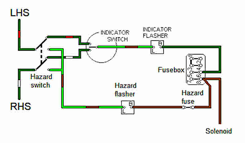
This (fairly simple) diagram shows one way.
http://www.mgb-stuff.org.uk/images/haz3.jpg
You have the hazard switch which, when engaged, connects both L and R to the flasher circuit and disconnects the indicator switch. The turn indicator switch is either off or it connects left or right to the flasher circuit (via the hazard switch).
The page that this is from has some additional ways to do it.
http://www.mgb-stuff.org.uk/s_hazard.htm
If you are still struggling, let us know how the blinkers are wired and share a wiring diagram if possible?
I’m no expert, just a hobiest with a basic understanding of electricity.
If I understand correctly, you basically bridged the turn signal bulbs together when you wired in the hazard relay.
I would install 2 diodes (12v 10amp or so) between the hazard relay and the turn signal bulbs. Diodes only allow electricity to flow one way, so it should prevent current from flowing from one bulb to the other through your wiring
Yeah that’s the only thing I can think of too. I don’t think the kit came with diodes which made me think I was misunderstanding something. Thanks! I will have to go with this unless there is another trick.
Edit: ended up going with diodes and it works great!
