

I thought I would knock some dust off my drafting skills after a small chat with @captain_aggravated@sh.itjust.works
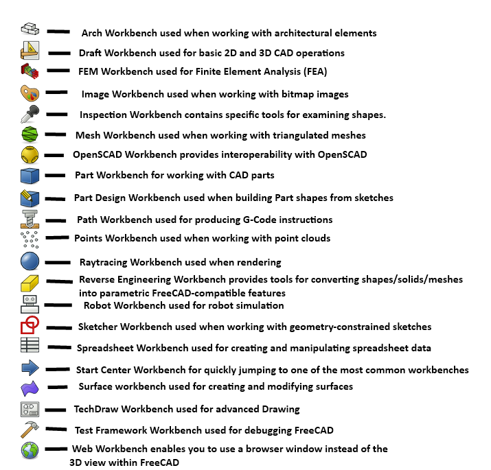
Seeing this image on the tutorial made me realize, FreeCAD seems to be a Technical Geometry Super-Suite. It makes sense that CAD would grow to include all of these things. But I thought sharing the initial perspective of some one who hasn’t looked at this stuff in about 18 years might be interesting.
Granted I’m not actually familiar with most of this stuff, and none of it from the POV of FreeCAD. If this can deliver 10% of what I’m looking at, I’m in for a treat.
Seems like a good opportunity to ask if anyone can recommend learning materials for FreeCAD? Used Solidworks and AutoCAD in school but fell back on tinkercad for a recent project just cause I didn’t have time to invest in learning.
This is a pretty good tutorial to get started in FreeCAD. Just watch out for the topological naming issue. They still haven’t fixed it, but if you know how to avoid it, you shouldn’t have too much trouble.
Parametric is such a leap, when coming from toy blocks like TinkerCad in which I can really easily do all that I want except those sexy fillets…
I really want to learn it but it feels so convoluted and difficult. I’m aware that FreeCAD is not the easiest, and some commercial packages are easier to grok but their licensing is really hostile to simple hobbyists so I am trying to to take the high road, for now anyway.
Hey, I have used freecad a lot. FreeCAD is good, not great as a cad software. But it is the only truly “no strings attached.” The problem with it was development was almost at a standstill for things that actually mattered. A new company has formed around commercializing it and are working with the original Dev team.
Updated UI, topological naming fix, some assembly and actual functional defaults were promised for Q1 2024 and releasing it as a 1.0 version.
I think it is worth it to learn how to use right now as in the next 2 years it should become an actual viable CAD alternative for things outside of simple projects.
I wouldn’t try parametric models in freecad. They use a really really bad spreadsheet reference system that recalculates you model, not on every change, but every CLICK which means that when you have a variable that is reference more than 10 times or so, it begins to take longer and longer to even start to enter a new value. One time it took 5+ minutes just to get into the spreadsheet cell before even being able to edit its contents.
For parametric, use OpenSCAD (or openscad in freecad) until they implement actual, working variables.
I wouldn’t try parametric models in freecad
I would clarify that you’re talking about a specific usage case, that OpenSCAD does indeed do better at. However for most CAD tasks I find OpenSCAD is overkill and less intuitive.
“Parametric design” usually refers to the workflow used in the Part Design workbench, as well as SolidWorks etc. where geometry is defined by constraints.
The Part Design workbench does work well and despite the topological naming issue is sufficient for most hobbyist and many light industrial tasks. If I need to draw up an arbitrary bracket or bushing or similar, I don’t even bother using a workflow that guards against the issue, I just use it casually like I would SolidWorks. Only if the part is complex or if I know it will need to be tweaked do I bother doing everything on datum planes etc. because it’s a lot slower and more hassle.
That’s very good news that the topological naming issue is being solved, though. #1 issue with FreeCAD IMO and the one that holds it back from serious industry use.
That’s how parametric workflows work in some industries. In the architecture world of Rhino / Grasshopper and Revit / Dynamo, the expectation is that parametric scripts can do almost anything.
If you don’t want to make parametric models, you can build simpler things by combining primitive shapes in the FreeCAD part workbench. You can even fillet and chamfer them.
The dirty secret of FreeCAD is that most drawings that look okay will extrude even if unconstrained. You just lose the ability to leverage the history tree and the model will be as brittle as any direct modeler’s.
FreeCAD is on its way, it’s attracting a little more money and attention, and I’m using it more and more, but I often still feel like I’m fighting it.
Mind. Blown. I had honestly not thought of that possibility. And you say fillets work? Wow, have to try that. Thanks!
I have found one issue with FreeCAD fillets: it doesn’t like it if they touch, that is…draw a rectangle with thickness of 10mm, and then apply a fillet around the top and bottom surfaces of 5mm radius, which would produce a perfect 10mm diameter. It doesn’t like doing that. 4.99 will work, but not 5.00. If you want a perfect half circle on the edge of something like that, you have to draw that another way.
That is an insane bug to have in your CAD software, I don’t see how it’s usable for any slightly complex part.
Literally every CAD program suffers this to a greater or lesser degree. There are workarounds but they’re clunky.
The issue with FreeCAD is that all the workarounds (so far) are manual. Other apps may well be doing similar things, but they’re doing them behind the scenes and the user doesn’t have to (for instance) specifically set up a datum plane offset at the exact same distance as the face you want to sketch on and either manage it by hand or use an integrated spreadsheet to set up and reference variables.
I like what I see coming out of FreeCAD these days, but stuff like that is… umm, a lot.
Here is an alternative Piped link(s):
This is a pretty good tutorial to get started in FreeCAD
Piped is a privacy-respecting open-source alternative frontend to YouTube.
I’m open-source; check me out at GitHub.
deleted by creator
I find that Onshape is quite good and is all browser based so it runs quite well on linux.
From my perspective the biggest thing wrong with FreeCAD is that it’s a single threaded app in a multicore world. If you load large stuff, the app freezes and one core is working really hard for a while.
Solidworks is the same way.
Can’t say I’m surprised.
No, it’s the topological naming problem. End of.
That doesn’t have me wait for tens of minutes while one core slogs it’s guts out and the other fifteen sit there idle.
Isn’t like every CAD program single core? People got scammed hard with Xeon in the past. CAD PC salesmen had/have absolutely no idea what they were talking about
Biggest speedup has been the GPU integration. The single core stuff doesn’t seem to matter much anymore.
Mastercam does pretty well once you force it to use hardware accelleration
Yeah if you want to be reductive about it, FreeCAD is a GUI wrapper for OpenCASCADE, its CAD engine. FreeCAD is designed to be extensible; the workbench system allows for several different workflows, and using the Python API it’s not that far out there to make your own workbench for specialized tasks. You could build a clockwork workbench if you were interested in designing escapements and such.
The tradeoff is it can seem overhwelming because there’s a LOT of functionality in there. I do almost all of my work in the Spreadsheet, Sketcher and Part Design workbench, plus the A2Plus assembly workbench from the addon manager.
Yeah OpenCASCADE is amazing because it’s the only real geometry kernel that’s open source. There’s a few smaller ones like solvespace, but they’re really more like toys. It’s like the Linux of the CAD world.
Writing a geometry kernel is a monumental task, not unlike writing a real os kernel or a modern web engine. I’ve seen people just lay the basic foundations of a kernel as their PhD thesis. Most of the commercial ones were written decades ago and are still being worked on - the big ones are Parasolid ACIS, ShapeManager, CGM. The last one would maybe be considered a newcomer cause it’s only 15-20 years old.
I just thought in hindsight, my response to you plugging freecad is funny.
It’s like you took me into your workshop with all these benches, and I just point at the openscad bench like a caveman and grunt “scad”.
Yeah somehow I never hitched horses with OpenSCAD; like I can’t imagine designing a table or cabinet purely through code. Using the Part Design workflow can work a lot like how tools work, lay out the location of the feature, draw the profile of the feature, then do an additive or subtractive operation to create the feature…the design process in basically any similar CAD package becomes a dress rehearsal for the build in a way.
That makes total sense. I was on my way to mechanical engineering when I was learning autocad and autodesk mechanical desktop if you remember that. Now it’s just in autocad. (I guess that’s an example of how things used to unshittify. I bet adobe would bring back MD as a separate product nowadays.)
So if you try to enter woodworking after that experience, it feels right to model projects like that. I had learned a lot of coding by this point. So adding the code into parts for flexibility felt great.
This is going to sound complicated. That’s because I bet you can do this with one click. But I thought it was cool I model a compound mitre angle for a cut using numbers I calc’d on Octave (matlab-like foss). Since I’m just a tinkerer, I could only imagine how powerful that could be for pros. Lots of “where was this when I needed it” thoughts.
Spreadsheet
Curious to hear what it’s like making parts with a spreadsheet. Is it like coding?
I use openscad a lot, and just tried using spreadsheets – adding parameters to each property in a part still seems really clunky, compared to editing a scad file in Emacs, which I vastly prefer, especially now that there’s AI code autocomplete.
It is very slightly like coding, it helps to understand Python’s syntax because as you get into things like the macro system and referencing cells in a spreadsheet, you’re skimming the upper atmosphere of FreeCAD’s Python API.
Just about every text box in FreeCAD where you can enter a dimension as a literal number, like using the dimension tools in the sketcher for example, you’ll notice a little f(x) button. That means you can also put in an expression as well. It can be as simple as “I don’t want to divide 6.675mm by four in my head right now” so you type in =6.675mm/2, or you can reference other objects. So you can do something like =overallThickness/2 to drill a hole halfway through something.
The spreadsheet workbench gives you somewhere centrally to put in values, do those calculations, things like that. You can then refer to them when sketching and part designing; say you name your spreadsheet “Sheet”, you can refer to a cell like =Sheet.B2. Or, you can give individual cells an alias, so you can have Sheet.overallThickness.
It works a bit like the Parameters feature in Fusion360, but more functional. It is a bit clunky out of the box, but there are a few macros available in the Addon Manager that let you highlight a column of cells, and it will apply the contents of each cell as the alias of the cell to it’s right, there’s another that allows you to click a line in the Sketch workbench, click a cell in the spreadsheet, and with one button click assign that cell’s value as the dimension, and it’s semi-smart as to what kind of dimension you need.
I find that doing it this way versus entering literal values into sketches puts all the dimensions in one place where I can read them all, and I don’t mix up values that happen to be the same but for different reasons, which can screw you over if you have to make an alteration later. “Ugh, I have to go through like five sketches and change all those 4.5mm dimensions to 5mm. Wait why is that wrong? Oh not THAT 4.5mm…” I also try to do as much of my math in the spreadsheet as possible instead of having them in sketches, partially because again they’re all in one place and easy to check, alter and fix, but also because that spreadsheet becomes a useful part of the set of drawings once I go out to the shop to build the thing I’ve designed. There are projects where I only printed the spreadsheet for reference in the shop. Note I forgot to list the Techdraw workbench, which is used to create dimensional drawings from your models, because sometimes I just don’t.
I use the spreadsheet to hold dimensions/variable and formulas, makes it easier to modify designs. If I want to change a length, hole size height etc just change the spreadsheet values don’t have to mess around with the sketches or 3d part designs directly.
One slightly frustrating thing i found is sometimes it fails to recompute the design or processes it incorrectly when values are changed by large amounts, that’s probably more to do with how I design things though
I’ve seen it do things like that for two reasons:
-
If your change causes the number or arrangement of faces to change, this currently breaks things. This is what people in this thread talking about the topological naming issue are about; it keeps track of which faces are which by giving them names when they are created, and then when another feature is added to that face, it’s linked by name. If you go back, edit an earlier step which creates more or fewer faces, it recomputes the model and might name them differently, so features suddenly move.
-
Sometimes I’ve had the sketcher just decide to turn a sketch inside out, because sometimes things like tangent constraints have two stable ways to be “fully constrained” or the existing constraints make different shapes with different dimension numbers.
I have seen both issues, when the sketcher starts to play up sometime I add more constraints to try to “anchor” a tangent in a certain direction but it can make the sketch messy The most reliable way I’ve found to stop it is small incremental changes e.g. say I want the length of a part to change my 40mm I’ll change the size in 5mm increments allowing FC to recompute the model between each step. It’s fiddly and frustrating but I can live with it, once you get to understand it’s quirks Freecad can be very useful
-
I often read that the UI is pretty unintuitive compared to the commercial competitors. I anyhow started with FreeCAD three years ago and never looked back. I design a lot of functional 3D prints with it and managed to solve all the issues I’ve faced so far. As I started with FreeCAD and never tried the alternatives, I also don’t miss the possibly more intuitive UIs 😁
I tried qcad around 2010 or so and found the UI horrible compared to autocad that I was used to. At this point in my life, drafting was pretty useless. So I had no reason to have cad unless it was free.
I found OpenScad in Y2020 and was amazed at how far it had come. It felt much more like the commercial stuff, at least to me, who was behind the times anyway.
QCad still sucks compared to AutoCAD, but it is only around $50 for a license where AutoCAD is pretty much subscription only at this point I believe.
We actually use it at work, because our 2d drafting use cases are very limited, but we still need something DWG compatible.
FreeCAD is fairly good. Some of the controls are a bit wonky, but that is just a minor gripe. If you are starting on FreeCAD, that doesn’t matter so much. FreeCAD is good to know if you design components for KiCAD as well.
Parametric modeling is fucking awesome, btw. I am not quite sure how old that concept is though.
Pretty old, I’d say 30 years. It’s what made pro/e, one of the first 3d cad systems, so famous within Boeing.
All 3D modeling software has absolutely terrible controls. I’m not sure there’s a right way to do it through a 2D interface.
I have seen people use pens and tablets for sculpting in Blender so that is an option. For my CAD work I do have a SpaceMouse but that is only really useful for large projects.
Until we get holographic projection (Iron Man style) I am not quite sure what a 3D system would look like, TBH.
At least a decade, probably more
Even Freecad is well over a decade old. Opencascade is over 20.
I’ve been only doing cad for about 10 years so my knowledge is somewhat limited. I was talking about parametrics specifically. I should have made that clear
Do they have editable history yet? That’s a big blocker for me jumping.
I was disappointed not to see one. That’s not a ‘no’, but I did look for one.
There’s basically a tree of operations that have been applied to a model. At any point, you can go back and edit what you’ve done at a previous step. For example, if you padded a feature out 10 mm, then added more stuff onto that feature, you could still go back and change that padding operation to 15 mm.
I’m still super new to freecad, and I haven’t done anything too complex in it yet, but my understanding is that some types of those changes can result in the topological naming problem. The way I understand it, when you make a shape, the software numbers all of the segments, vertices, and faces. If later changes are applied to those numbered faces, etc, and you go back and redo the operation that made those faces, etc, in a different order, the numbering will be different, and it will break your model.
There is a fork of freecad that fixes that whole issue, but the fix hasn’t been implemented yet in the main fork cause it’s pretty foundational to the working of freecad, so there’s a lot of things that can break
If you just attach every object to the global coordinate system instead of each other that bug can’t happen. Could be less convenient for larger projects though
I believe the company ONDSEL that is pushing development is pushing that together with its collaboration tools as the SAAS component of their freeCAD soft-fork
Further define “editable history?”
I use Fusion 360 primarily but it is available in other CAD software, this is a decent description:
Timeline and Rollback: The timeline in Fusion 360 visually represents the design history, showcasing the sequence of features and operations. You can review, reorder, and modify design steps using the timeline. The rollback feature allows you to return to a specific point in the timeline and make edits, facilitating design iteration and exploration.
It has made working on interactive designs significantly easier for me, and saves a tremendous amount of time and effort.
Ever used photoshop with an undo history? It’s particularly nice for text based commands.
Needs a better logo as well
Actually that’s a great place for some “I want to help but I don’t know computers” people to jump in.
Yep, there’s a ton of great Foss projects that have a shitty logo. Look at Octave, looks like something 10yo me made in MS paint in 5 min
Logos, GUI, names…
Hey now, naming things is in NP-hard.
My architect so poked at it for a bit and quickly gave up.
That part at least isn’t suited to its target audience apparently.
Can it export STL/3MF without making all the circles low poly yet?
Last time I tried it freecad was not usable for 3d printing because it doesn’t export properly.
With the naming bug that still exists too I found it basically unusable even for basic parts. It feels like going back 20 years compared to fusion 360.
I’ve used it for making models for 3D printing for about 5 years, never seen that issue
Strange, when I looked it up at the time there were a bunch of suggestions for defaults to change and stuff to try and solve it.
You can print circles and not have them come out with flat faces instead of an actual circle?
So I guess it’s only an arc and not a full circle, but I had no problem making this curved sanding block in FreeCAD.

deleted by creator
Yes. I just did a few days ago actually. Made some 4 mm diameter washers, they look perfectly round.
Have you tried using the mesh workbench rather than just exporting as STL?
STL is a total abnormally and a piece of shit of a format that doesn’t actually represent 3D objects very well and has a ton of issues when it comes to sharing. Unfortunately we’re stuck with this shit format and Autodesk with their Tinkercad seems to want to keep pushing it because as long as we use this crappy format we’re forced into sharing and collaborating inside their platform - that at some point might require a subscription.
Completely agree about STL, however, I cannot for the life of me understand why 3MF isn’t a binary format.
It has all these big tech companies behind it, and they landed on incredibly short sighted mistake of making the format human readable, instead of providing good tools for reading and modifying the binary format.
Compressing the human readable content is fine for reducing storage size. But de/serializing the XML is going to be at least 3 orders of magnitude slower. Given a sufficiently large file, the difference would be waiting 30 seconds, vs a barely noticeable 0.3 seconds.
What isn’t variant of XML these days? I know, it’s bad but it’s what it is.
XML isn’t as common as one would think. It’s been steadily decreasing in popularity and use. It’s a very verbose format that is suited to enrich a larger set of data, such as HTML documents. For data heavy documents where, it’s a particularly bad match, as you end up using as much text for annotation as the data itself.
Using XML for 3MF is IMHO a technical cop-out, where you don’t really want to solve it “correctly”, so you go with something that is “good enough”. With XML, you know it’ll be able to encode anything, be human readable, and have existing parsing libraries in pretty much any programming language and standard libraries. So, it makes sense. However, if you’re creating such a format, the least one should do, is write a sibling standard for how to directly binary encode the data. This isn’t a hard thing to do. It just need a standard for how to do it, so everyone agrees. Here is an example online on how a rudimentary implementation could be done for OBJ files, but the principle is the same. That way you could chose to export either as 3MF or 3MFB (for binary), and as long as your slicer, and what not, can decode it, you’re good.
The hard part of 3MF was all the great work in standardizing what, and how that is represented.
I noticed a similar problem importing step files… I no longer had circles, I had nonagons… I would love to delete my windows vm that only exists for fusion 360.
If you are comfortable with all your models being available for download and some wonky Terms of Use that may let random internet people profit off your designs but not you, then OnShape in a full-screen browser feels about as good as F360 does. I guess you could also pay for it, but despite finding it pretty nice, I am iffy about paying Solid Edge prices for something browser based. I understand SolidWorks has slapped together a browser version as well, but nobody likes it.
Linux wise, there’s just not much outside FreeCAD and SolveSpace. BricsCAD is an okay evolution of AutoCAD, and VariCAD is a less good one.
I may have done a longer writeup than anybody needed the other day.
I have tried out onshape and it is a pretty functional fusion replacement, but I really don’t like the idea that the models I make can be used (or even just sold) by others commercially. I’d be okay with it if the free version just gave all models made with it an open license that barred commercial use entirely, but banned for me and open for sale by others is pretty dirty imo.
The sense I get is that it is more lazy than anything. The verbiage feels like the fact that designs were public documents was tacked on last minute to satisfy some desire for market segmentation or to create a parts and design library to draw traffic. It would make sense that the company hosting the software would not want the headache of being unable to use your stuff commercially or even of parsing what they could use, since in some sense they always are using everything commercially. Refusing the to thread the needle with their verbiage, though, has left a situation where the Terms of Use say clearly that (1) a design is Content, (2) a free user’s Content is a public document, (3) a free user cannot use their own public documents for commercial use, and (3) a free user grants EVERY OTHER USER a license to sell their public documents.
- “End Users’ files, designs, models… (collectively, “Content”).”
- “All documents created by a Free Plan User, and all Content contained therein, is made public and therefore considered a Public Document.”
- “If you intend to use the Service outside a trial context to create and/or edit intellectual property for commercial purposes (including but not limited to developing designs that are intended to be commercialized and/or used in support of a commercial business), then you agree to upgrade to a paid subscription to the Service.”
- “For any Public Document owned by a Free Plan User… Customer grants a worldwide, royalty-free and non-exclusive license to any End User or third party accessing the Public Document to use the intellectual property contained in Customer’s Public Document without restriction, including without limitation the rights to use, copy, modify, merge, publish, distribute, sublicense, and/or sell copies of the Document, and to permit persons to whom the Document is made available to do the same.”
The only possible wrinkle is that the ToU distinguish between a “Customer” and an “End User,” so maybe you the customer can grant you the End User the same commercial rights that Joe the slightly shady CNC machinist in Peoria has when he downloads your widget to fabricate and sell. Something tells me that PTC’s license compliance folks don’t interpret things that way, though.
When I tried it like 7-8 years ago it crashed pretty much every time I touched a constraint. Was I probably doing something very wrong? Yes, but that made it pretty impossible to learn. Opposed to Fusion360 which just yells at you when you do dumb shit.
Sounds like it was only five years behind SolidWorks. The CAD program with one level of Undo, an unreliable Revert option, and active hostility toward incremental saves. It was great for machining because every change was about as permanent and slicing up actual metal.
The CAD program with one level of Undo, an unreliable Revert option, and active hostility toward incremental saves.
I don’t know the first thing about CAD, but lmao.
Not the first four letters that came to mind.
Last time I tried freecad, the geometry solver was incorrect, so it would sometimes create two (or more) shapes from a fully constrained part. Since learning about openSCAD, I’ve seen no reason to give it another try.
Yes, I’ve 3d printed circles from freecad without issue. There are some precision options when converting to a mesh. I always set them to the tolerances of my 3d printer.
Overall, it still has a lot of rough edges though.
I don’t mean to poo poo FreeCAD the way I say this, but the vast majority of those features listed are bog-standard cad suite features at least by modern standards.
I’d love to see a FOSS cad suite kill my personal dependency on proprietary solutions, but as best I’m aware the UX is still hugely lacking.
Does FreeCAD handle aerodynamics? A decade ago I wanted to screw around with low-speed airfoils, and couldn’t find any better indications than ‘OpenFOAM and good luck.’
Great piece of software, but still nowhere near the beauty of PicoCAD
As a programmer, OpenSCAD is amazingly easy to use compared to the mouse based alternatives


