
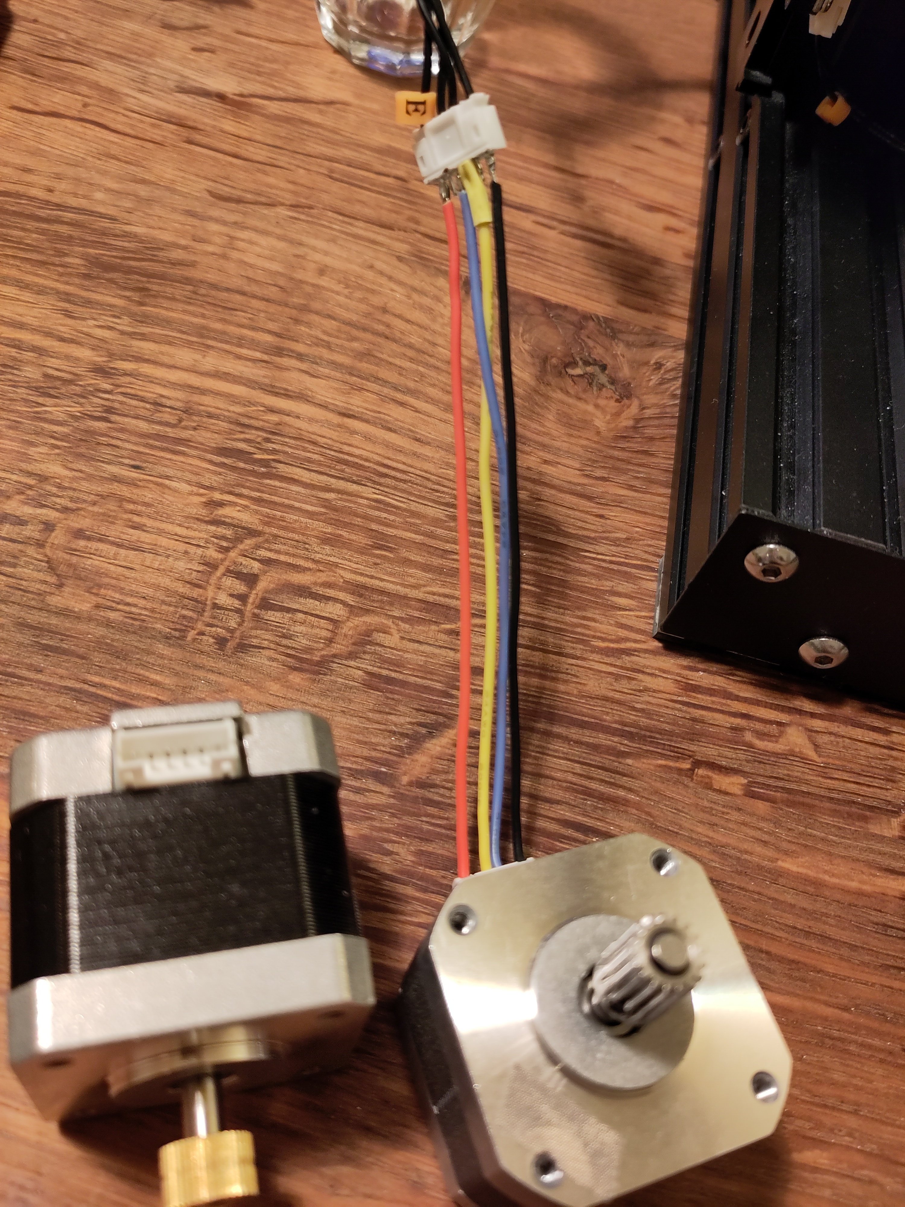
I just got an old Ender 3 for cheap and wanted to replace the crappy extruder with a nicer bowden extruder of my (now) direct drive Kobra Max. When I connect the new stepper, nothing moves. It’s a longer stepper and a different manufacturer. Is the wiring different or VREF wrong or are there other reasons why it wouldn’t move? The driver is good, since the old stepper is still working.
Thanks for any help!
NEMA motors should all have the same wiring, it’s part of the standard in the nema specs, might be off on voltage, which would make sense. Check the specs on your motor and pull out a volt meter and check/adjust its voltage to match the new motor’s needs.
As long as both have the same number of wires, that is.
This is, of course assuming the physical connections are all dandy. (It’s possible something came loose in the conversion?) you’ll have to open its case up any how to get the volt meter on the tuning pot anyhow. (Positive to the pot, negative to ground somewhere. I’d drop a guide but specifics change with boards.)
Just to give more details, NEMA 17s can have 4, 5 or 6 wires. 4 wire versions are bipolar while the 5 and 6 wire versions are unipolar. While it would be nice if NEMA 17s were all the same, they aren’t. The standards apply to dimensions but not electrical specifications. Windings will change from manufacturer to manufacturer but are ultimately limited by its size. Because of this, all NEMA 17s will be capped in torque to a degree. Increase the case size with a NEMA 23 and you get more space for more windings, etc.
More info here: https://www.etechnophiles.com/guide-to-nema-17-stepper-motor-dimensions-wiring-pinout/
Edit: All this said, it doesn’t matter too much if steppers are mismatched. It’s just a matter of tuning voltage and steps. I prefer to have the same steppers in a project since it is much easier to configure that way.
deleted by creator
To clarify what I meant, the Pinouts are all standardized- or should be. OP shouldn’t have any issue slotting in the old wires (unless it’s a different wire count, of course.)
If it is a different number of wires OP will certainly be having a hard time adapting it… (that becomes a firmware issue; and I just don’t want to know the headache a creality main board will cause with that.)
Pinouts aren’t standardized in my experience. You get 4 wires but the color and position can be different. OP can easily use a multimeter to find the two pairs and then use different combinations to find the correct placement (1A,1B,2A,2B - 1A,1B,2B,2A - 1B,1A,2B,2A - etc)
Ok, so wire count is the same. I guess the remaining problem is current limit then?
probably, unless you’ve managed to get a bad connection or something- just something to look at when you’re opening it up to get to the pot. try and see if you can check the voltage specs on the new part, compare it to where its at. It’ll save you a lot of grief if you know where it should be before hunting around for it.
Afaik steppers don’t care about voltage. It’s about current since it’s all inductors inducing magnetic fields.
Nearly all stepper drivers deliver a constant current to the motor, or at least, it tries. While the nominal voltage needed for a stepper is essentially “irrelevant”, setting the correct voltage determines the current available for the stepper, by the driver. This gets a little different to work out since the current is generally “clipped” or “chopped” as part of the function of the driver. (Ohms law is only really applicable to a stepper motor when it is not moving, btw.)
A minimum voltage is still required to overcome back-EMF.
Without going into the maths, your voltage settings determines your available current, basically.
Steppers require a certain amount of voltage to maintain position, too little and it looses position/starts shifting, too much and it overheats and stutters.
Generally, steppers will only draw what they need, and not more. 3d printers usually have current limiting switched if something goes weird.
Pinouts are not standard (at least in practice). I’ll downvote your post for it to not appear on top.
I use a tevo tornado which is similar in many ways to an ender3 and added a direct drive extruder. I ended up needing to change the wiring for the stepper motor because it just sat there jerking around but not moving. I don’t recall if I used a meter to measure resistance or if I just swapped wires until I got it working but it prints perfectly today and has for years.
To do it I think I had to use a small screwdriver to push in the little barb that holds the pin in the connector (on some you can lift a little plastic tab on the connector to pull it out) then I could just push it back in place. Make sure you don’t disconnect your stepper while powered, it can toast your controller.
I checked the pinout with a multimeter yesterday and the don’t seem to be the same. I’m pretty sure this is the issue. Thanks for mentioning pinout as a source of issues.
I created an adapter and now it’s working like a charm! Thanks a lot!
Glad I could help! I know it’s really frustrating when you’re right at the 99% mark and it’s like “why isn’t this working?!”
New Lemmy Post: Stepper not moving (https://lemmy.world/post/10365552)
Tagging: #3dprinting(Replying in the OP of this thread (NOT THIS BOT!) will appear as a comment in the lemmy discussion.)
I am a FOSS bot. Check my README: https://github.com/db0/lemmy-tagginator/blob/main/README.md
