
5·
6 months agoThank you both! Hopefully get to come out with even more crazy fun ideas soon!
The Meep and the Merp of www.skree.us, www.etsy.com/shop/TheBigSkree, and Skree LLC.
I make keyboards, hydroponics that no one has seen and lots of cool pcb / mass production solutions. Reach out if you want to discuss anything.
Thank you both! Hopefully get to come out with even more crazy fun ideas soon!
Not that I’m aware of but the DRC systems should be able to make it pretty clear if there’s track issues.
There are circuit / electrical simulators but that’s a very complicated solution for keyboard designs that tend to be simplistic.
Matrix circuit designs are not much to be worried about. If you had a design in question I’m sure someone including myself would be willing to look at it.
What kind of plastic? If PLA 3D Gloop PLA works amazing. Otherwise hotglue, or my suggestion is don’t do single key pcbs / handwiring (ad) I make flexible pcbs for curved keywells (specifically used them on my dactyl keyboards I’ve sold, hundreds in the wild without any issues! www.skree.us or etsy.com/shop/thebigskree if you’re interested in that. (I ship internationally but it can sometimes take a while to arrive).
If the micro controller works with the software (ZMK / QMK / KMK etc) then yes, it works. Both of those would work.
Enjoy?! Heck yes. What a build!
Wired I can do more of. Just order two I have spares for the extras I’ll gladly just include. The actual cost in time is minimal for the extras.
Non-transparent they’ll do light sanding to. Transparent they come with supports removed, but there is very fine markings where supports attached to the model.
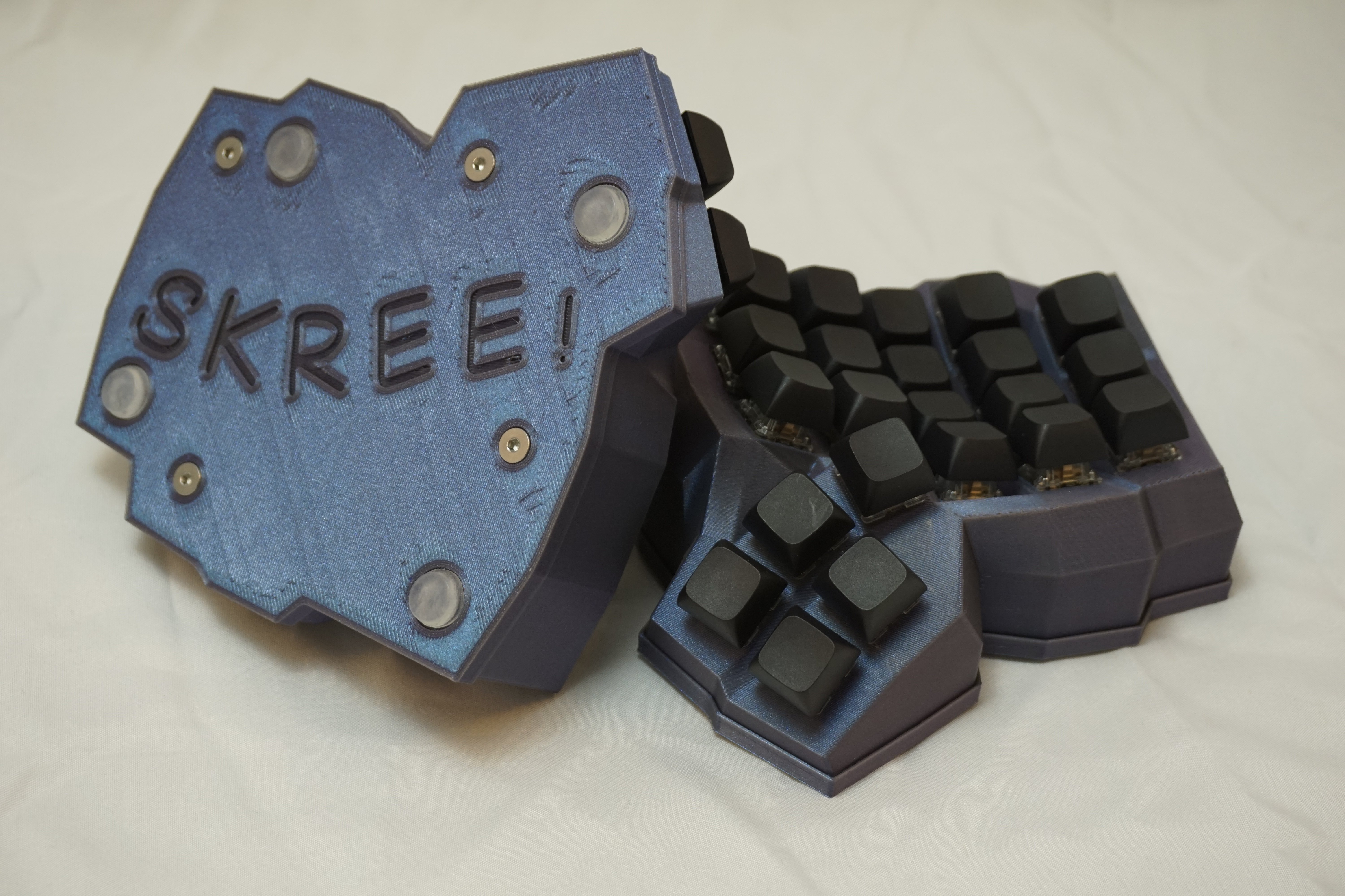
Yep, just cut. Super simple to do, right at the start of a flex strip. I’ve got lots of things going on! I sanded the verticals on one half for a frosted effect. The other half I have to prep and figure out what clear coat I’m going to spray on it. Been utterly distracted doing the pick and place machine (got my flexible pcbs populated with diodes) learning how to do multiple components is going to be the next step.
As in 5 rows 7 columns? My flexible pcbs can be linked together for infinity columns.
https://www.etsy.com/listing/1367143291/dactyl-flexible-pcbs-4-and-5-high I’m out of populated 5r pcbs but I just got the pick and place machine populating diodes (I’m short on hotswaps but they’re super easy to solder).
QMK or ZMK?
I’ve used ZMK reset and bootloader keys for well over a year.
Should work fine. If you’re worried I can print a single column cut from the skeletyl to test.
Kill your board? No! They’re all data pins, so there isn’t current to kill anything unless you short to the PCB or a battery somehow!
I make flexible pcbs with hotswap for dactyls (and other curved / flat keyboard production). They save oodles of time, and make troubleshooting easier too! All you need is a little hotglue on the edges to lock the pcb fully in place (I have a screw version produced too just need to get a good source of screws to include).
Handwired builds, especially uninsulated are more prone to shorts that will cause unexpected switch behavior. PCBs even per key help minimize that risk.
Not 100% sure on if you can easily get this consistent. I know that there are ways of dying resin post print though.
I wonder if you can just get evenly tinted semi-clear automotive for it.
SK6812 Mini-E (they’re the big legs, but I don’t know the component name difference).
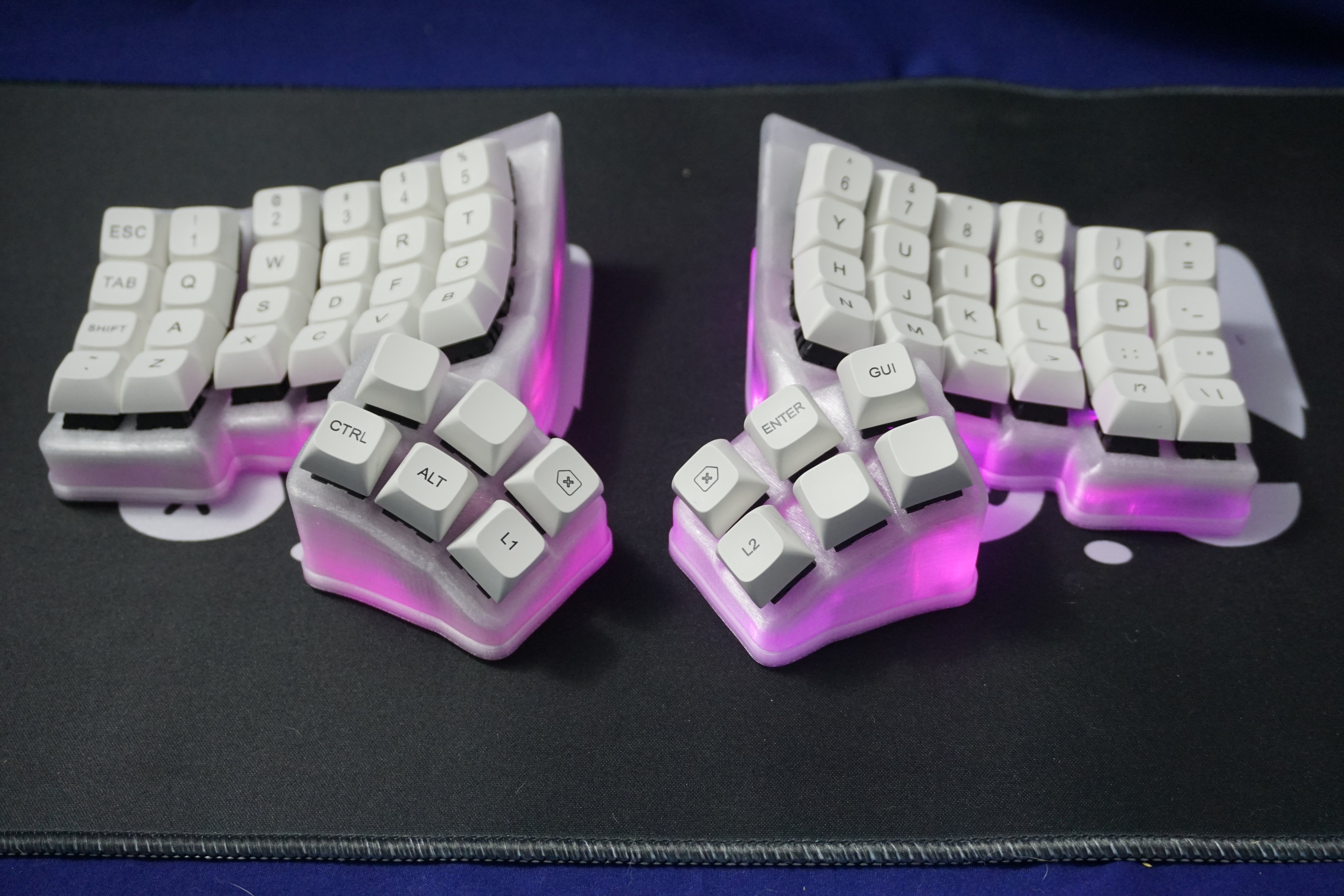
They can be per key (not supported on ZMK currently) or just treated as up facing underglow. BUT! The biggest concern I’ve had is the realization thaht all RGB boards on the market that use SK6812 in bulk don’t seem to consider the total peak power consumption.
One color can peak at 12ma at 5v. They’re often ran at 3.3 or 3.7v. 3 colors per led for 36ma per led. So on sofie type boards where there’s ~30 keys per half you’re pulling 1.08ma if you ran the leds at max white. This would be HIGHER if they’re run on 3.3v or 3.7v due to the relationship between wattage and voltage. Yet! They’ve worked fine. I’ve had good success.
Going forward I’m swapping to SK6805 surface mounted leds. I’ve got the pick and place running, and the goal is to have per key rgb with underglow. That would almost 1/3rd the amperage requirements. Also gives me a little more board space I’m hoping.
Ideally, I’ll have non-rgb options, up facing perkey rgb, underglow, and up and underglow rgb options (probably 2 independent rgb channels aka underglow has its own data pin). All in either Choc v1, MX, and whatever else I decide to support.
I’ve got a working “screw” mount solution that works! The problem is with the pcbs fitting super well (model dependent) (I’ve based on the standard dactyl) why bother using lots of screws when a little hot glue does the job. My first versions were wrongly sized and I ended up being extra cautious with lots of extra glue to ensure there’s never a issue with pcbs coming free, but at this point I’ll either cut the number of screw points down, or honestly supply it but not use it myself.
The nice thing with getting access to production equipement (my designs are all about saving my time in production) you get to save that time too.
Sorry for the silly long response!
It’s resin from JLCPCB. My small resin printer just can’t do a 5x6 sadly. The first transparents I had done was with PETG.
Sadly, JLCPCB doesn’t do tinted black, but honestly a clear coat with a little black alochol dye probably would do the trick.
I was blown away with the quality from JLCPCB. It’s not that expensive but shipping hurts. Holes aren’t perfect, but my switch dimensions worked great surprisingly. I need to do a little more work getting the threaded inserts I have fully working (might have to drill potentially because I didn’t expect the oval circles). Their texture really confuses me. I legit don’t know for sure what technology they’re using for their resin prints.
It can be a pain. That and tuning supports so they don’t fail, or slice you up trying to get them out.
Jumping in here to say I’ve worked with Wylder for quite some time now. He’s quick witted and really knows his stuff!
Are you feeding the leds with 5v or 3.3v? I’ve had issues with 5v and no shift registers as the led won’t pickup the high state of the leddata without a shift register.
https://github.com/WainingForests/zmk-config-xiao/tree/Xiao_rgb I have successfully done LEDS just fine. Per key is a misnomer though. ZMK doesn’t allow individually addressing each key. Instead, you’ll be using underglow to apply effects to the whole “chain.”
Cut it up! Print only thumbs for a while that you can “locate” to a standard set of finger keywells. Do the same for other features you’re wanting to customize.
I can also relatively easily tweak the pcb dimensions if needed to fit. Including switch center to center “flat” distance!
Thanks! I’m trying my best and my hard work on pcb design seems to be providing pretty good outcomes!