Hello everyone, I need some advice.
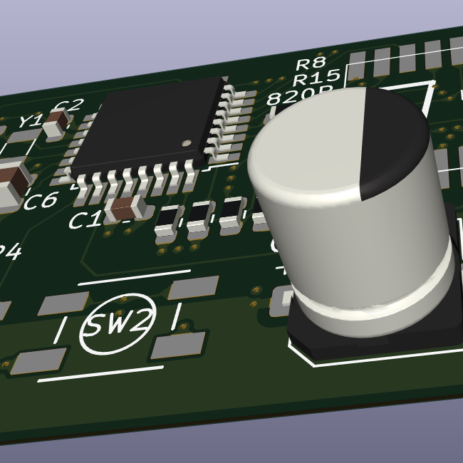
I am making custom PCBs for a project of mine. It’s basically for a little remotely controlled robot using little DC motors. I chose the Seeed Studio XIAO ESP32C3 as the uC since it has inbuilt wifi/bt, 3.3V regulator that I can use to power the motors (can source up to 700mA) and lipo charging management (the robots will run on battery). As you can see from here, the microcontroller is surface mounted and the pads for the battery are on the bottom layer. Same story goes for the thermal pad of the microcontroller and the thermal pad of the motor driver (datasheet). I have worked with SMD components in the past and can solder them by hand, but I have never worked with SMD components that have thermal pads on the bottom layer. My question is: how to manage (route?) them? My PCB is 2-layer and I was planning on having both layers filled with a ground plane. Do I just connect thermal pads to the ground plane and call it a day? Wouldn’t that make the components hard to solder with hot air? Do I make an isolated polygon that only acts as a thermal pad?
Speaking of soldering is even hot air the way to go in this case? My PCB has components on both sides, and I was planning on ordering stencils together with the boards and using solder paste, placing the components and then using hot air to solder the components in place. I thought a hot plate would be better but I don’t have access to one and I don’t know how that works with components on both sides.
I attached some photos of the PCB in Kicad, and here’s the git repo. If it is of any help, I’m planning of having them manifactured by JLCPCB. It is also my first time using KiCad, so go easy on me :)
Thanks!


Yup, the thermal pad is usually connected to ground with multiple evenly spaced vias
What are the sizes for your via and traces you are using btw?
Edit: I would also make the first one all on the same side unless it’s really crucial it stays that small, it’s generally not advised to put components on both sides unless you have no choice. It will make routing and your gnd plane simpler. If your gnd plane is Swiss cheese, it doesn’t really do its job properly and might actually cause other weird problems.
0.8mm (size) / 0.4mm (hole) vias
Trace width depends on the net class, I calculated them using kicad’s built-in calculator
- 0.127mm (minimum by jlcpcb) for signals and low current
- 0.15mm for motors (the max. current the driver can source is 400mA per channel, I overspec’ed them since my motors will absorb current in the order of 100mA)
- 0.3mm for power supply
I also need that the PCB stays as small as possibile, so having components on both sides is a necessity for me
I usually try and go a bit higher for trace size than needed to avoid complication and aid in heat dissipation. My signals are by default .25 and my power traces are usually between .5 and .75 (my teacher argues for 1 and 1.5).
There are trace width calculators online like on digikey that can tell you he minimum you need.
Your vias are fine though, I usually go 0.5/0.3 . If you bring up your power traces, you have to keep in mind a vias hole should be the same size or bigger than the trace.
I also edited my other comment while you were replying, sorry.
Just saw your comment on the PCB size. In that case I would definitely go with a four layer board to avoid issues (heat and signal integrity).
The vias are there to transfer heat to a solid gnd plane to properly dissipate it mainly but not all components need them. I usually add them anyways but the datasheet should tell you on their example footprint, some components even tell you specifically not to.
If you have components on top of each other, I think it’s better to forego them instead of linking two relief pads together but maybe with a solid gnd plane in between, it’s okay.
I also just saw how they places their vbat and gnd on your main chip, I don’t think I would put any there either unless it asks for it.
If you have pics of the schematic, I can take a deeper look at it. Cool project, first time I see that chip.
I also just saw how they places their vbat and gnd on your main chip, I don’t think I would put any there either unless it asks for it.
What are you exactly saying here? You wouldn’t put vias behind those pads?
Just saw your comment on the PCB size. In that case I would definitely go with a four layer board to avoid issues (heat and signal integrity).
Yep, I’ve also done some tests with ground planes on both layers, and it comes out sparse to say the least. Problem is, I have never made a 4-layer board, do you have any resources on those I can learn from? Are there any particular things to pay attention to? How do I “organize” layers? Which ones do I use for traces and which ones for power planes?
If you have pics of the schematic, I can take a deeper look at it. Cool project, first time I see that chip.
Here’s a quick screenshot, in the original post I linked the git repo which includes all kicad files. It’s rough atm, I haven’t made it look good yet

On second thought, i would move S2 a bit and put vias on pad 17 of U1, I would also put vias on the thermal pad of IC1.
Using multiple layers is actually simple. You want your top layer to be signal, then your two middle should be gnd and vcc with the bottom being an other signal layer. Gnd and vcc planes makes routing easier since you can just add vias next to any power pad to connect them to their respective plane. Audio boards in particular will sometimes have both middle planes be gnd instead, with vcc routed with the signal on the other planes. It helps with signal integrity, but gnd/vcc planes is whats used much more.
In kicad, under file, then board setup; the first one is how you add them (board stackup/ board editor layers). You just need to check In1.cu and In2.cu and indicate they are power planes. Then you have to select them with the layer selector on the right and draw power planes on them. Once the zones are filled (hotkey B), any gnd or vcc via should connect to the appropriate plane.
I really like Phil’s Lab, he has mostly advanced videos but he explains really well and goes in depth. https://www.youtube.com/watch?v=QAOEtfvCaMw Skip to 9:58
Last thing, it’s hard to tell what packages you use but I would make some of the components a bit bigger to make your life easier since you have a bit of space. I try to avoid going below 0805 for anything I might be soldering or desoldering by hand.
I disagree with his otherwise great advice: make the two middle planes GND, route your power and signals on the outermost layers.
The closer your gnd plane is to your signal or power lines, the lower the inductance and the increased resistance to emi. Otherwise any noise on the vcc plane is separated from the gnd plane by about a mm, vs being less than 0.2mm away from the gnd planes if they’re the two middle layers.
The copper is also usually thicker on the outer layers and you have access to atmospheric cooling.
The copper is also usually thicker on the outer layers and you have access to atmospheric cooling.
The copper is thicker on OSHPark’s outer layers, but its thinner (!!!) on DKRed’s outer layers.
Just an FYI in case other people here are USA-based and want to use USA-based PCB makers. Yeah, that’s right. DKRed has thin 0.5 oz outer layer copper and 1oz inner-layer copper. I’m guessing DKRed is aiming at the Gnd-signal-signal-Gnd style boards… while OSHPark’s 4-layer stackup is better for signal-gnd-gnd-signal.
Look at your datasheet, but put some thought into it too… I like to segment the heat via, breaking it so that the heat dissipation isn’t infinitely large.
In other words: vias that can wick heat to the other side of the board, and on that other side, a smaller gnd plane made by breaking the connection to the rest of the gnd plane.
Not sure if it’s helpful, but bigclivedotcom recently reverse engineered a toy with vias between layers for thermal transfer:
https://www.youtube.com/watch?v=qTeZVqoVe7U&t=257 at 4:00+
Hadn’t seen this technique in use before - but I know just enough to begin to know what I don’t know…